How the GSM system works?.
By admin
GSM.
In various countries the frequency bandwidths specified for the GSM services are GSM-400, GSM-800, GSM-900, GSM-1800 and GSM-R.The GSM-900 and the GSM-1800 are the most widely used frequency bandwidths in different parts of the globe.
The GSM-900 has a down link frequency range of 935-960 MHz and an up link frequency of range of 895-915 MHz. This frequency band is partitioned into 124 pairs of simplex channels with separation of 200KHz.A particular range of simplex channels is given to a particular network provider.
The type of interface used in GSM is digital air interface.The analogue voice signals are converted to digital signals before transmission.Up to 8 MS subscribers can be handled by the GSM RF carrier at a time.The rate of transmission is 270 Kbps.
The Gaussian minimum shift keying (GMSK) is used for transmitting the digital signals.In GMSK , a phase change represents the change from a digital “1 ” or a “0 “,occurs over a period of time.The addition of high frequency components to the spectrum is reduced.In GSMK ,the phase change is not constant and it is spread- out.
—————————————————————————————-
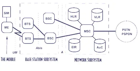
Schematic of a GSM system.

SIM - Subscriber Identification Module.MS - Mobile Station.ME - Mobile Equipment.BTS - Bare Transceiver System.MSC - Mobile Services switching Center.NSS - Network & Switching Subsystem.PSTN - Public Switched Telephone Network.
By admin
GSM.
In various countries the frequency bandwidths specified for the GSM services are GSM-400, GSM-800, GSM-900, GSM-1800 and GSM-R.The GSM-900 and the GSM-1800 are the most widely used frequency bandwidths in different parts of the globe.
The GSM-900 has a down link frequency range of 935-960 MHz and an up link frequency of range of 895-915 MHz. This frequency band is partitioned into 124 pairs of simplex channels with separation of 200KHz.A particular range of simplex channels is given to a particular network provider.
The type of interface used in GSM is digital air interface.The analogue voice signals are converted to digital signals before transmission.Up to 8 MS subscribers can be handled by the GSM RF carrier at a time.The rate of transmission is 270 Kbps.
The Gaussian minimum shift keying (GMSK) is used for transmitting the digital signals.In GMSK , a phase change represents the change from a digital “1 ” or a “0 “,occurs over a period of time.The addition of high frequency components to the spectrum is reduced.In GSMK ,the phase change is not constant and it is spread- out.
—————————————————————————————-
Schematic of a GSM system.
SIM - Subscriber Identification Module.MS - Mobile Station.ME - Mobile Equipment.BTS - Bare Transceiver System.MSC - Mobile Services switching Center.NSS - Network & Switching Subsystem.PSTN - Public Switched Telephone Network.
Mobile incoming call indicator
By admin
Description.
This circuit can be used to escape from the nuissance of obile phone rings when you are at home.This circuit will give a visual indication if placed near a mobile phone even if the ringer is deactivated.
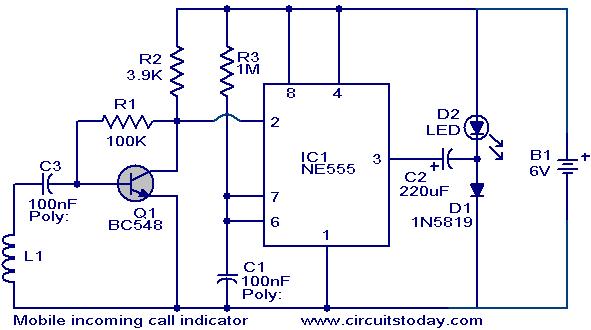
When a call is coming to the mobile phone, the transmitter inside it becomes activated.The frequency of the transmitter is around 900MHz.The coil L1 picks up these oscillations by induction and feds it to the base of Q1.This makes the transistor Q1 activated.Since the Collector of Q1 is connected to the pin 2 of IC1 (NE555) , the IC1 is triggered to make the LED connected at its output pin (pin 3) to blink.The blinking of the LED is the indication of incoming call.
Circuit diagram with Parts list.

Notes.
The coil L1 can be made by making 150 turns of 36 SWG enameled copper wire on a 5mm dia plastic former.Or you can purchase a 10 uH coil from shop if available.
The circuit can be powered from a 6V battery.
Assemble the circuit on a good quality PCB.
C1 & C3 are to be polyester capacitors.
The electrolytic capacitor C2 must be rated 10V.
By admin
Description.
This circuit can be used to escape from the nuissance of obile phone rings when you are at home.This circuit will give a visual indication if placed near a mobile phone even if the ringer is deactivated.
When a call is coming to the mobile phone, the transmitter inside it becomes activated.The frequency of the transmitter is around 900MHz.The coil L1 picks up these oscillations by induction and feds it to the base of Q1.This makes the transistor Q1 activated.Since the Collector of Q1 is connected to the pin 2 of IC1 (NE555) , the IC1 is triggered to make the LED connected at its output pin (pin 3) to blink.The blinking of the LED is the indication of incoming call.
Circuit diagram with Parts list.
Notes.
The coil L1 can be made by making 150 turns of 36 SWG enameled copper wire on a 5mm dia plastic former.Or you can purchase a 10 uH coil from shop if available.
The circuit can be powered from a 6V battery.
Assemble the circuit on a good quality PCB.
C1 & C3 are to be polyester capacitors.
The electrolytic capacitor C2 must be rated 10V.

No comments:
Post a Comment